How to apply FPM algorithm
Automated Point Positioning for Robotic Spot Welding Using Integrated 2D Drawings and Structured Light Cameras
Lu Deng, Huiguang Wang, Ran Cao, Jingjing Guo
College of Civil Engineering, Hunan University, Changsha 410082, PR China
Abstract
Precise point positioning is crucial for implementing robotic spot welding. Traditional 2D drawings of structural components lack depth information, making them insufficient for guiding robotic welding. This paper introduces an automated robotic welding framework for spot welding based on 2D drawings and structured light cameras. To enhance the efficiency of point positioning, a new algorithm was also developed with a spatial complexity level of log4(N), where N is the resolution of the image. Three different 3D cameras with distinct imaging principles were used in the experiments, and their performances were compared and discussed in detail. The proposed framework was validated against a scaled experiment, where the positioning accuracy by the proposed method met the code requirements. It was also found that the proposed vision-based welding approach could provide similar accuracy in welding orientation estimation as light section sensors but at a much lower cost.
Keywords: Point positioning; 2D drawings; Supplementation of depth information; Stud welding; 3D vision
Tutorial
The first step: Extract 2D drawing coordinates information from .dwg files

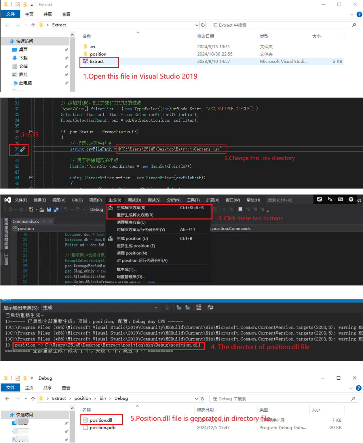
1. Compile .dll file: Initially, we should download Visual Studio 2019, then just open our code in Visual Studio 2019. It is noticeable that you should change your .csv file save directory in line 11. After that, you can compile .dll file
2. Extract 2D welding coordinates information: Initially, we should download Visual Studio 2019, then just open our code in Visual Studio 2019. It is noticeable that you should change your .csv file save directory in line 39. After that, compile .dll file
3. Output 2D welding coordinates information .csv file: There is a video in Youtube which can be referred to how to use position.dll.[Video]

The second step: Map 2D welding coordinates to 3D space: FPM algorithm
We have open sourced all codes in Github, and the structure of program as shown below
FPM_code
├── 1_TargetPointExtract              # file includes programs aimed to identify mark board
|  ├── Camera2Robot.txt               # the homogeneous matrix from Camera frame to robotic arm world frame
|  ├── CenterExtract.py               # main program aims to identify circular marks
|  ├── circle_info.txt                # The identifications results of Hough-Transformation Method
|  ├── ColorMap.png                   # RGB image of the mark board
|  ├── DepthMap.tiff                  # depth map of the mark board
|  └── mark.png                       # The identifications results (RGB image)of Hough-Transformation Method
├── 2_Cad2Base                        # file includes program aimed to transform 2D coordinate from local frame to world frame
|  ├── Cad2Base.py                    # main program aims to transform 2D coordinate from local frame to world frame
|  ├── Centers.csv                    # 2d welding coordinates in CAD frame
|  ├── Centers_modified.csv           # 2d welding coordinates in local frame
|  └── Transformed_Centers.csv        # fianl results: 2d welding coordinates in world frame
├── 3_MainProgram                     # main programs include BFS and FPM algorithm to map 2D coordinates
|  |  ├── BFS.py                      # BFS algorithm
|  |  └── FPM.py                      # Fast-Pixel-Matching algorithm
|  ├── Camera2Robot.txt               # the homogeneous matrix from Camera frame to robotic arm world frame (A area)
|  ├── ColorMap.png                   # RGB image of A area
|  ├── DepthMap.tiff                  # depth map of A area
|  └── Transformed_Centers.csv        # fianl results: 2d welding coordinates in world frame
├── API                               # Application Programming Interface
|  ├── Came2End.txt                   # the result of eye-in-hand calibration
|  ├── Camera2Robot.txt               # the pose of camera
|  ├── CameraIntrinsics.txt           # the intrinsics matrix of camera
|  ├── Rigid_transformation.py        # an API for rigid transformation
└──└── UR10_robot.py                  # an API for controling robotic arm
1. Identify the circular marks: We recommend that just ultilize the results as shown in file: circle_info.txt. Because program: CenterExtract.py can be run when it connects with robotic arm and camera. Additionally, we draw the results of identification in mark.png.
2. Transform 2D coordinates from local frame to world frame: Centers.csv file includes 2D welding coordinates in CAD frame, which can be extracted by the AutoCAD plug-in. Transformed_Centers.csv is the final results of running program: Cad2Base.py.
3. Map 2D coordinates to 3D space: We provide two method in filefold 3_MainProgram, including Brute force search (BFS) and our method: Fast-Pixel-Matching (FPM). Actually, you just run BFS.py and FPM.py.
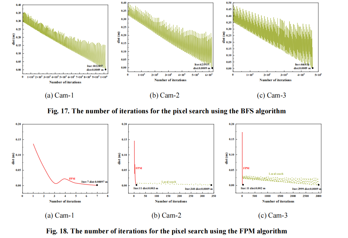
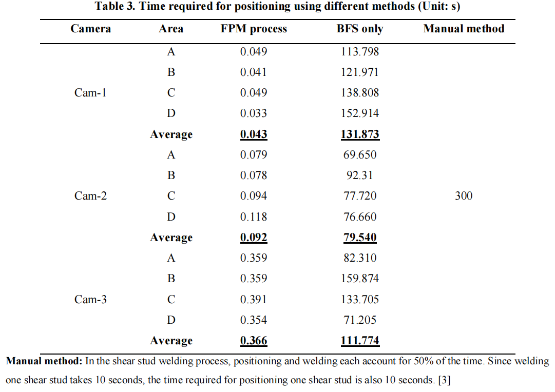
Finally, several typical results of FPM algorithm are shown below, compared with BFS method.


If you have any questions, please contact me without any hesitations at: whg0917@hnu.edu.cn


Leave a comment